If you have any questions about my articles or our products (or just want to chat about golf car repair), feel free to contact me at guru@golfcarnews.com.
Question: S.K. Writes: Mr. Kramer can you please help with some sort of bench testing for controllers so we can run them before we install them?
Answer: Continued from September/October 2014 issue. This time around we’ll address a shunt wound motor test stand and wiring.
Parts:
1 Single Pole Double Throw Switch
3 Single Pole Single Throw Switches
1 5K to 0 Potentiometer (Linear 3 Pin)
1 Project Box (Plastic)
1 1/4” Knob
1 Sheet Of Wood Or Plastic (36 X 18 X 3/4”)
1 Stand (36 X 25”)
1 36/48 Volt Battery or Ferro-Resonant Transformer
1 Assortment Of Color Tape
1 Assortment Of 18/22 Color Wire
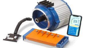
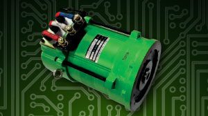
1 Shunt Wound Motor (Closed Case)
1 36/48 Volt Contactor
1 In-Line Fuse Holder
1 Controller Mounting Plate (E-Z-GO Heat Sink)
1 Assortment Of Six Gauge Cable (Lugs)
1 Assortment Of Wire Ends
1 Speed Sensor Lead Cable
1 Assortment Of Molex Connectors And Pins
1 Amp 23 Pin Male Connector
1 Pre-Charge Resistor (For Controllers That Require)
1 Diode For Contactor (Spike Protection)
1 ITS Module
The Project Box, Tape, Switches, Knob and Potentiometer can be purchased at Radio Shack. Wire, Cable, Lugs and Wire Ends you should have in your stock. You can use a motor from your stock just add the end plate. Molex and AMP Connectors, Pins and Sockets can be purchased on-line at Mouser, Digi-Key or Allied electronics. You can build a table or see what Harbor Freight or Lowes has. The battery is Lithium-Ion and may not be in your area and it is handy. Any of your old Ferro-Resonant battery chargers you can use. All you need is the transformer and diodes. Power connections are connected as Manufacturer recommends.
The key to any test stand is knowing the switch pin-outs and controller pin-outs. It is important to know the sequence of operation. Based on any given system whether it is GE, Alltrax, or Curtis each one has its own pin-out configuration. As you build your wiring adapters you must consider that. Basically, you will need as I call it the “Known Factors”. As you can see by this simplistic diagram are a sequence of known factors. Power supply, run/tow, key, forward/reverse, throttle and potentiometer. Typically, you will see 8 to 10 potentials you will need to work with. Every controller has to have a positive input voltage. Usually, that is either direct from run/tow, key switch and foot switch. Then you start with forward/reverse inputs the system uses. If you look at this drawing you only see positive inputs and outputs. Negative pre-exists in controllers internally. Negative controller output usually only consists of just one or two signals. Such as drive the main contactor or back up alarm. For this test stand we only care about contactor input. Know what this input is and label it clearly. It is important to have the correct wiring diagram of the system you are working on. Each car manufacturer has diagrams that clearly show the controller pin-outs. Taking those pin-outs and aligning the adapter pins with controller pins can be easily done. Think ahead and look at each configuration and plot out the different adapter to controller circuits. Unknown factors can be throttle inputs or speed sensor inputs. If you look at the simple POT (potentiometer) in the drawing it is a basic linear design and can be used as 5K start or 0 start depending on full turn clockwise or full turn counterclockwise. Other inputs can be voltage or inductive design. You just have to know what the manufacturer is using.
The reason you want to make removable connections is so you can use the switch box for trouble shooting golf cars. As an example the above box is for E-Z-GO ten pin Controller. Connect the Molex ten pin to the controller. Connect the red wire to battery positive. Connect the Blue wire to contactor negative input side. Connect the Yellow wire to contactor positive input side. Turn switch K (Key) on, then switch T (Throttle) on. Connect pins 1 and 2 to an ITS module. If the car runs from slow speed up to high speed this eliminates the Controller, Motor and Conductors. Result, this is telling you there is an issue in the car wiring or throttle. Note: use a steel rod to simulate throttle.
You can do this same thing with the other Switch Box and adapter per application. The Potentiometer I chose is usable either as 5K to 0 or 0 to 5K wipe. It can be wired as high or low side input with center wiper. If you wish to have the car run in reverse push switch R. If you wish to test the ITS circuit just clamp a wire piercing test lead to the throttle wires pin 1 or 2. You should see 14 volts on one side and .9 volts on the other pin. As you insert the steel rod you should see that low side voltage of .9 (lower than 1 volt) climb from pedal up to pedal down close to 3 volts. If you see this voltage movement then the controller is working in terms of throttle. If you do not see that voltage the controller or ITS is defective. I would use a diode in pin 10 wire and key switch input. And do not forget some brands of controllers require a Pre-charge resistor and a KSI Diode for Contactor coil voltage spikes.
For further assistance just send me an email and I will help you.