This is a multi-part question and answer.
Question: I have a 1999 Club Car DS that when I turn on the switch and put it in F or R and depress the foot pedal I can hear the solenoid click but it will not move at all. When I replaced the controller the solenoid was not clicking. Now all I get is the click but nothing is moving. I checked out the motor and it tested well but I did have another one here so I replaced it just to be sure. Still is not running. I looked at the F/R switch and it seems to be working properly. Any ideas?
Roger Asks: Series or Shunt? Meaning, does the car shift with a lever or rocker switch? I have to know that before I comment.
Roger, It has the rocker switch, and it has two solenoids. The second solenoid without the spring resistor (the driver side solenoid has the spring type Resistor) is not working at this time. I am going to swap it with a new one and see if that helps. I am not very familiar with this specific setup and I am not certain what that second solenoid (on the passenger side) does. But I do know that through all of the functions it never made contact.
Answer: That is called Regenerative Braking System 2 (Power Drive Plus) and is the second generation Shunt Wound Motor System often referred to REGEN 2. Now we can talk.
System Pin-Outs:
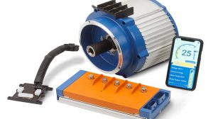
To test this system it is just a matter of confirming pin-out voltages. Notice the controller has a 23 pin connector and each pin has a voltage value. You will need self-penetrating wire leads as shown in the photo. The industry has moved into that style of testing and you can purchase at Grainger, Digi-Key, Mouser Electronics or any electronic supply warehouse. The right tool makes the job easier. I made a view of the 23 pin for ease of recognition and as a guide. But refer to Club Car chart for exacts, and the connector is numbered.
As with any trouble shooting procedure you must confirm the Known Factors. Later you look for Unknown Factors.
Known Factors:
• Knowing what positive inputs we see at pins 1 and 2 if we do not have a positive voltage at that point we have an open in the Run/Tow wiring and or switch.
• Knowing what positive input we see at pin 3 and if we do not have a positive voltage with the accelerator pedal pushed the accelerator pedal wiring or switch is open.
• Positive input should be seen at pins 4 and 5 and if we do not we have loss of voltage in the forward and reverse wiring or switch.
• Used on Club Car is a positive OBC input to power up the system (pin 6). It can also be used as a key switch positive input.
• The Potentiometer inputs at 7, 8, and 9. Pin 7 is the wiper, pin 8 is negative (low side) pin 9 is positive (high side). The voltage value is listed in the appropriate PDP diagram. Or you can do a resistive reading on a 20K scale at pins 7 to 9. You should see 5K to 0 pedal up to pedal down.
• Positive pulse at pin 14 from the speed sensor. This is typically a 5 volt pulse and is very difficult to see and difficult to test. Mainly just confirm a voltage is present.
• Positive voltage at pin 15 that Club Car says in 5 volts G.E. refers to it being 12 volts. Just confirm you have a constant voltage. If that voltage is missing that means the controller is not sending that voltage.
• Negative output at pin 16 to the speed sensor. If missing the controller is not working based on good inputs.
• Negative output at pin 17 for solenoid activation. If missing the controller is not working, inputs missing or computer lock out is seen.
By knowing the pin-out values we can locate the problem.
The unknown factors missing voltages. As an example of missing voltage say at pin 3. That is not the controller that is the foot pedal circuit. Foot switch or associated wiring. What other wiring or switches are in that same circuit? Looking at the diagram we see a key switch and run/tow switch in that same circuit. So you have to test that circuit to confirm where voltage is missing.
Unknown would be pin 6 output/input from and to the on-board computer. That is the lockout from the computer and shuts car down when on charge. What I do on those is cut that yellow wire and then, connect a positive to it and see if the car runs. If so you have a defective computer. See the correct PDP diagram for other computer wires needed for by-pass (not just signally the yellow wire at pin 6).
So finding Unknown Factors are done after Known Factors is completed.
Yes the customer did repair the car!