Q: BH From R.I. Asks: How do I bench test a Marathon Ignition system?
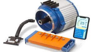
A: BH, the way I do that is by the use of a Marine Plastic Board and mount the following items. Use a 10597 Pulsar Coil, 5121 Coil, 9174 Spark Plug Wire, and either or 10594/10595 Igniter. Add a Normally Open switch for activation. Add a Plunger style solenoid like you would find on a Carburetor shut off. On the end of the solenoid plunger glue, solder or crimp a flat piece of metal. Connect a spark tester onto the coil wire and ground. It is important to gap the Pulsar magnet to the solenoid flat metal piece. You may need to adjust that a few times to get it to exact. I placed mine at .030†and at times need to close that gap a tad or open it a tad. You just have to make adjustments as you go with that part of it.
Looking at the system and how it works will give you some insight as to functionality. Any ignition system must have a power source of 9.6 volts up to 16 volts for proper testing. Confirm that first. You can purchase a 12 volt power supply from your local Radio Shack or electronics outlet store. Once an applied voltage of positive and negative are in place. A positive voltage is applied to Igniter and coil. Battery negative (ground if you will) is applied to the base of each component and direct to the igniter internal circuit. By activating the solenoid the magnetic field causes a signal (voltage) to the igniter. This signal then causes a voltage to the ignition coil. Then you should see a good solid blue spark on the tester. The faster you can “click†the solenoid on and off the faster the spark will be. So imagine on a spinning engine at 3000 RPM’s how quickly that all happens! So you can kind of think of that circuit as a “pulsing†voltage. So if you have a failure of spark your next step is to confirm potential voltage at each point in the diagram. It is next to impossible to see the voltage pulse but you can see a spike. That spike usually indicates the component is sending a signal (voltage). But that voltage must make and break in order for the system to work. Base the test stand on a working set of components before you use it on suspect parts. I tested over 100 igniters with this and it does help with bench testing.
Interchange from 10595 to 10594 to 10595. Both units use the same Pulsar Coil and this makes both units compatible with the system. The one noticeable difference between the two units is the D wire color. 10595 is a black wire and the 10594 is a red wire. All other wires are matching colors. Cut the wire ends and add the appropriate connectors to each wire and route each wire to the correct component in the system.