HQ Writes: What is the simplest Shunt System on the Market?
According to Roger:
This is the simplest shunt system ever built and has the highest failure rate
(in our system). We had several calls on this just this last week! Seems it is quite popular.
Step one is confirm the battery pack voltage is a nominal voltage of 36 volts. 38 volts is fully charged. Make sure the batteries can maintain a voltage under load above 34 volts. Low voltage will not allow the logics to activate.
Step two is confirm all pin out and pin in values going to the controller activation circuit or power circuit. This is called sequence of operation. Confirm you have 36 positive volts at the contactor large terminal coming from the battery pack. Missing, the cable is defective or the battery pack is defective or dead batteries. We just checked that in step one. Confirm there is less than 36 volts positive on the other large contactor terminal. With the Pre-charge resistor in place. If there is not a pre-charge resistor the value should be zero volts. Activate the system, (key on, in forward and accelerator pedal pushed). The contactor should “click” and you should read full 36 volts positive. If you do not read 36 volts positive or increase to 36 volts positive (with resistor) the contacts or defective in the contactor. Replace it.
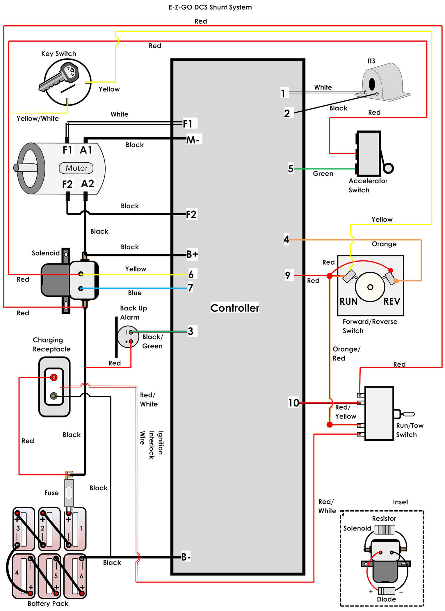
If the contactor will not activate that is in the activation circuit. Confirm you have positive voltage at pins 5, 6, 9 and 10. This is done with the key switch on, in forward and accelerator pedal pushed. If you are missing positive voltage at pin 9 or 10 you have an open in the run/tow switch, wiring, or ignition interlock switch. If the interlock switch is open just move the red/white wire to battery positive and add a 10 amp in-line fuse. If you are missing positive voltage at pin 6 there is an open in the key switch, run switch or wiring. If you are missing positive voltage at pin 5 you have an open in the footswitch, wiring, key switch or run switch.
At this point we have one pin-out that is negative voltage. Based on all the positive inputs being present. We need to confirm there is 36 volts negative at pin 7 going to the contactor. If that negative voltage is missing either the reverse switch/wiring or controller is defective. From the reverse switch you should see a positive voltage at pin 4 at activation.
Step three is confirm the ITS (inductive throttle sensor) is functioning. Based on all the pin-out’s and ins are correct that we just did. You should see 13 to 15 volts at pin 2. If you do not the controller is defective. If voltage is correct then check voltage at pin1, it should be .3 +/- pedal up and at pedal down close to 1.6 +/- volts (positive volts). If you do not see that voltage the ITS is defective. Sometimes you will see the white wire on pin 2 and the black one on pin 1. That means nothing, just use the pin number not wire color as color is irrelevant.
Step four is confirm you have a negative voltage of 36 at cable connection B-. If not the batteries are dead or a cable is open.
Step five activate the contactor. You should have full positive voltage at M-. If you do not check motor brushes or there is a defective FET inside the controller. Or, remove A1 cable (can be A2) and see if you have full positive voltage on the cable. Sometimes those cables are switched. If no voltage the motor is open or the armature brushes are worn out. Email me for motor test procedure.
Step six is turn run/tow to off. Disconnect the battery pack. Remove F1 and F2 wires on the controller. Place an ohmmeter across those two wires (low ohms). You should read 1 to 3 ohms. If you do not the fields are open or shorted. If the reading is good check the motor for grounds. If that is good replace the controller.
I am sure I did not write every little detail down and you will have to improvise a tad. The point to this is PROCEDURE. Just step by step confirm voltages. By doing that you will locate the problem area. This test procedure has never failed me. Note: The testing procedure for the ITS is just a surface test. I suggest going a tad deeper with that test. That is almost a subject in itself and I may do a more complete test procedure just for that. Email me for more ITS information.
Caution: DO NOT JUMP THINGS OUT! Use all safety precautions (do not assume)!
This covers the major details, but you will have to improvise, the point to this is PROCEDURE. For more information, please feel free to email me at guru@golfcarnews.com.